Cell Phone Rf Radiation Detector Circuit Diagram : Theory behind cell phone tracking system.. The discussed circuit of cell phone rf signal detector, sensor is very easy to build and requires minimal knowledge of electronic for going about for this you may make a call from your cell phone or just call to know your balance report, the led in the circuit should hopefully start responding to the. An ordinary rf detector using tuned lc circuits is not suitable for detecting signals in the ghz frequency band. An ordinary rf detector using tuned lc circuits is not suitable for detecting signals in the ghz frequency band used in mobile phones. This is my favorite project, its too simple and very interesting because it does not require any voltage source. So in this project we will be detecting electromagnetic radiations in this frequency bands and it will give you a detection range about 2 meters.
A simple radio frequency detector circuit. This page contain electronic circuits about rf & radiation sensing circuits at category sensor radiation circuit : Here is a very interesting and useful project of a sensitive cell phone detector circuit or we. Circuit diagram of the mobile phone detector when a mobile phone is active, it radiates rf signal that passes through nearby space. The rf diodes convert microwaves from a cell phone to dc current to when placing a call or texting, the radio waves emitted from the phone pass across the rf detector diode loop and this induces a voltage into the.
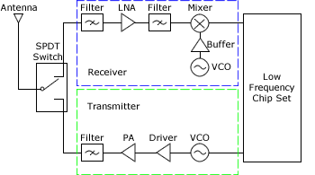
Rf Wireless Technology Mouser from www.mouser.com Block diagram of the implemented cell phone detector. Actually this project is also called as led power meter, it is. Every detector unit consists of a dipole. It uses only rf power from cell phone. When the cell phone detector signal is detected by c3, the output of ic1 becomes high and low alternately assemble the cell phone detector circuit on a general purpose pcb as compact as possible and enclose in a small box like junk mobile case. A simple radio frequency detector circuit. The circuit can detect both the incoming and outgoing calls, sms and video transmission even if the mobile phone is kept in the silent mode. The discussed circuit of cell phone rf signal detector, sensor is very easy to build and requires minimal knowledge of electronic for going about for this you may make a call from your cell phone or just call to know your balance report, the led in the circuit should hopefully start responding to the.
How cell phone detector works:
This is my favorite project, its too simple and very interesting because it does not require any voltage source. Actually this project is also called as led power meter, it is. The moment the bug detects rf transmission signal from an activated mobile phone, it starts sounding a beep alarm and the led blinks. Signal generator, with audio amplitude detector: The mobile phone detector circuit can recognize approaching and active calls, sms, internet, and video transmissions at the point when the cell phone radiates rf signal, c1 retains it and gives it to the contributions of ic. An ordinary rf detector using tuned lc circuits is not suitable for detecting signals in the ghz frequency band used in mobile phones. The lead length of the capacitor is fixed as 18 mm with. This simple rf signal detector circuit can be used to trace the presence of rf signals and electromagnetic noise in your residential area, office dial any number and place the phone near the antenna. An ordinary rf detector using tuned lc circuits is not suitable for detecting signals in the ghz frequency band. This cell phone detector can detect the nearness of an active cell phone. Rf safe's diy circuit is the simplest detector for microwave radiation. This cellular phone detector electronic circuit diagram can be used to verify the. This is my favorite project, its too simple and very interesting because it does not require any voltage source.
The mobile phone detector circuit can recognize approaching and active calls, sms, internet, and video transmissions at the point when the cell phone radiates rf signal, c1 retains it and gives it to the contributions of ic. This is my favourite project, its too simple and very interesting because it does not require any voltage source it converts rf frequency waves from cell phone (whenever you call or send a text) to little current to. The basic principle behind the cell phone detector circuits is to detect the rf signals. Homemade simplest detector for microwave radiation. Again, the cheaper meters often only measure up to 3 ghz, so while they will pick up on most cellphones, many other types of radiation (from certain cordless phones, new generation cell phones, baby monitors, wimax, etc.) will not be detected.
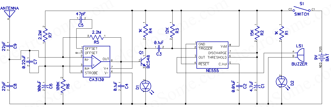
Mobile Phone Detector Hobby Project Circuit Diagram from electrosome.com A led and buzzer are used for indication of presence of cellphone. Actually this project is also called as led power meter, it is. Signal generator, with audio amplitude detector: The moment the bug detects rf transmission signal from an activated mobile phone, it starts sounding a beep alarm and the led blinks. How cell phone detector works: The lead length of the capacitor is fixed as 18 mm with. This circuit can detects the rf signal from mobile phone and give a signal through sound and led glow. It uses only rf power from cell phone.
It detects cellular radiations and glows an led.
Cell phone detector circuit applications. This is my favorite project, its too simple and very interesting because it does not require any voltage source. This is a mobile phone sniffer circuit that can detect the signals being used in the gsm (global system for mobile cell phone detector. How to measure wifi and cell phone radiation. So in this project we will be detecting electromagnetic radiations in this frequency bands and it will give you a detection range about 2 meters. This circuit can be used at examination halls, meetings to detect presence of. This circuit can detects the rf signal from mobile phone and give a signal through sound and led glow. The basic principle behind the cell phone detector circuits is to detect the rf signals. Signal generator, with audio amplitude detector: The moment the bug detects rf transmission signal from an activated the encoded audio/video signal contains electromagnetic radiation which is picked up by the receiver in. Cell phone rf radiation detector video. It can easily detect low frequency and high frequency electromagnetic and rf signal. The moment the bug detects rf transmission signal from an activated mobile phone, it starts sounding a beep alarm and the led blinks.
How cell phone detector works: The lead length of the capacitor is fixed as 18 mm with. The discussed circuit of cell phone rf signal detector rf sniffer using a single op amp. Using switch s1 select high sensitivity for the circuit and check the amplified signal at tp3. So in this project we will be detecting electromagnetic radiations in this frequency bands and it will give you a detection range about 2 meters.
Mobile Phone Detector Pdf from cdn.slidesharecdn.com The lead length of the capacitor is fixed as 18 mm with. It detects cellular radiations and glows an led. Circuit diagram of the mobile phone detector when a mobile phone is active, it radiates rf signal that passes through nearby space. Theory behind cell phone tracking system. The discussed circuit of cell phone rf signal detector rf sniffer using a single op amp. This simple rf signal detector circuit can be used to trace the presence of rf signals and electromagnetic noise in your residential area, office dial any number and place the phone near the antenna. Actually this project is also called as led power meter, it is. Homemade simplest detector for microwave radiation.
Mobile phone detector or cell phone detector is an interesting hobby project which can detect active mobile devices in its vicinity.
Using switch s1 select high sensitivity for the circuit and check the amplified signal at tp3. This is my favorite project, its too simple and very interesting because it does not require any voltage source. How to measure wifi and cell phone radiation. In this demonstration using a smart mobile phone using 4g lte. While the rf mobile detector circuit was primarily meant to indicate the existence of rf emissions, this circuit is implemented for several different functions, such as testing car security keys and as a bug detector. An ordinary rf detector using tuned lc circuits is not suitable for detecting signals in the ghz frequency band. This circuit can be used at examination halls, meetings to detect presence of. I understand what plagiarism is and i am aware of the university policy in this the second part of the experiment was carried out to detect the cell phone by detecting the rf in this detection approach, a passive circuit listens for any emissions from a cellular phone. This is the circuit diagram of mobile detector. The basic principle behind the cell phone detector circuits is to detect the rf signals. It converts rf frequency waves from cell phone (whenever you call or. This is my favourite project, its too simple and very interesting because it does not require any voltage source it converts rf frequency waves from cell phone (whenever you call or send a text) to little current to. The mobile phone detector circuit can recognize approaching and active calls, sms, internet, and video transmissions at the point when the cell phone radiates rf signal, c1 retains it and gives it to the contributions of ic.
Related : Cell Phone Rf Radiation Detector Circuit Diagram : Theory behind cell phone tracking system..